
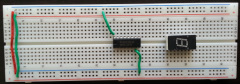
1. The negative and positives of the breadboard were connected.

2. 7447 IC and 7 segment display were both added to the circuit.

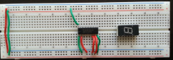
3. Pin 8 of the IC chips was connected to ground along with pin 16 being connected to high .
4. Inputs A, B, C, and D were added to pins 7,1,2, and 6 of the 7447 IC chip
5. Pin 1 of the 7-segment display was connected to pin 13 of the 7447 IC chip

6. Pin 13 of the 7-segment display was connected to pin 12 of the 7447 IC chip

7. Pin 10 of the 7-segment display was connected to pin 11 of the 7447 IC chip

8. Pin 8 of the 7-segment display was connected to pin 10 of the 7447 IC chip

9. Pin 7 of the 7-segment display was connected to pin 9 of the 7447 IC chip

10. Pin 2 of the 7-segment display was connected to pin 15 of the 7447 IC chip
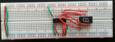
11. Pin 11 of the 7-segment display was connected to pin 14 of the 7447 IC chip

12. Pin 3 of the 7-segment display was connected to pin 14 of the 7-segment display

13. 100 ohms resistor was connected from pin 3 of the 7-segment display to 5 volts

